Introduction
In this lesson, you will explore different types of connectors found on the ends of cables that are used to connect the various audio recording components together. Some are going to be more common than others but they will, most likely, show up at some point in your setup. Whether you use them or not depends on your component configuration. Often there is more than one way to create a connection and there are many ways to create a hybrid connection; like a cable that has one type of connector on one end and another type of connector on the other end. What’s that you ask? Why are we learning about connectors when we don’t have any idea of what to make the connection to? A very good question, indeed.
I decided to put the connection information here for the following reasons:
- It gives you time to contemplate the myriad of different connectors.
- It allows you to absorb the information about the connectors.
- You will reinforce your knowledge of connectors as we progress through the rest of the lessons.
- You will make the connection when the time comes.
So there you have it. While you might not realize it, when you start learning about the components in greater detail, you will again come across these connectors, by then they will have been sleeping in your memory and you will reinforce that information about the connectors when the information is revived. Then again, if for some reason the connectors didn’t make it to long-term memory storage, you will be able to have a second chance at doing so.
Finally, connectors and the cables they are attached to, are the proverbial highways between cities that link everything together, allowing for the transport of inter-component commerce.
Part I - Connectors
The XLR Connector
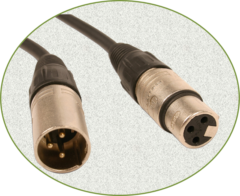
The XLR connector is one of the most common connections in a recording studio. This connector is commonly seen with microphones and their cable. If you go to an audio store and ask for “mic cable” it will most likely have this connector. The XLR is a balanced connector under normal wired conditions. However, sometimes a studio will rewire cable and connectors for a modified purpose but in your case, this should not be a problem.
XLR connectors can also be used for things like monitors and even keyboards, synthesizers, and effects processors. Typically the higher end products use such connections. If not, they will use the 1/4-inch Phone plug (balanced).
The 1/4 Inch Phone Plug TRS (Balanced)
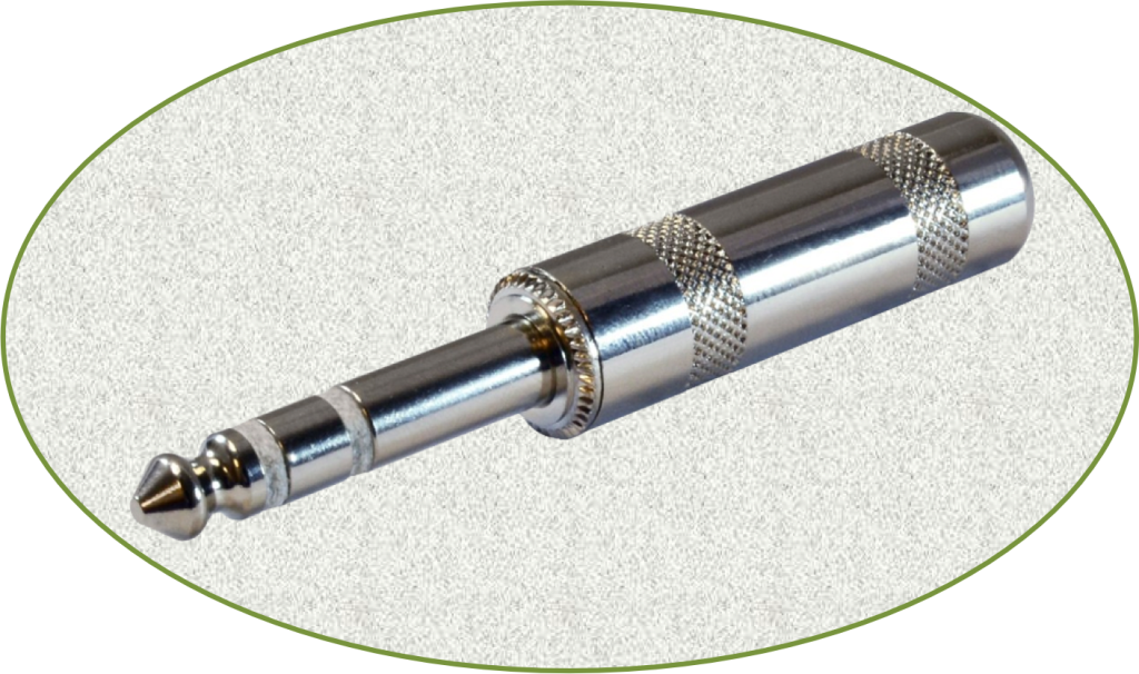
This is the 1/4 inch Phone Plug TRS (Balanced). It is also known as a 1/4- inch stereo phone plug. The reason is that this plug has the ability to carry a stereo signal as well as a mono signal.
So, why do they call it “TRS and Balanced?” If you look at the plug, there are 3 sections to it. The very end is known as the “tip” the next section is known as the “ring” and finally, the section next to ring is known as the “sleeve.” So, TRS = Tip, Ring, Sleeve: Too easy. The balanced part is a little more complex but I will try to keep it as simple as possible without getting too technical.
Think of a balanced connection as carrying the same signal x 2. The way it is able to do this is by splitting the signal and inverting it. So, remember how I said that the TRS phone plug has three parts? Well the first part the sleeve (pin 1) is the ground. Pin 2 carries a “hot” signal and the Ring (Pin 3) carries a cold signal. So a cold signal is the same as the hot signal except that it is an inverse wave whereas, it is similar to looking at your self in the mirror. However, unlike the image in a mirror, the cold signal is real and not merely a reflection.
The advantage of using this type of connector is that you are basically doubling your signal and therefore, the signal can (A) travel longer distances and (B) creates a stronger signal because of the doubling effect (think 1 + 1 = 2).
One final thought, you noticed how I said “pin 1, pin 2, and pin 3? Well, those pin numbers are the same pins used on an XLR connector. So, the XLR connector is the same type of connection (balanced), it is just a different connector.
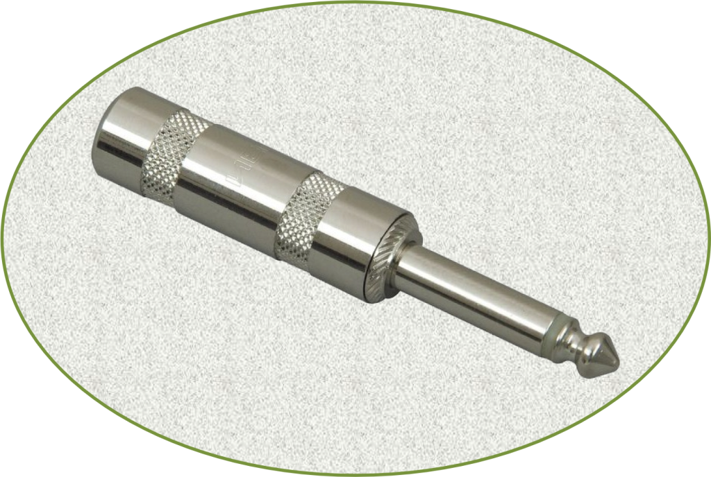
1/4 Inch Phone Plug TS (Unbalanced)
This is the 1/4-inch Phone Plug TRS (Balanced). It is also known as a 1/4-inch stereo phone plug. The reason is that this plug has the ability to carry a stereo signal as well as a mono signal.
So, why do they call it “TRS and Balanced?” If you look at the plug, there are 3 sections to it. The very end is known as the “tip” the next section is known as the “ring” and finally, the section next to ring is known as the “sleeve.” So, TRS = Tip, Ring, Sleeve: Too easy. The balanced part is a little more complex but I will try to keep it as simple as possible without getting too technical.
Think of a balanced connection as carrying the same signal x 2. The way it is able to do this is by splitting the signal and inverting it. So, remember how I said that the TRS phone plug has three parts? Well the first part the sleeve (pin 1) is the ground. Pin 2 carries a “hot” signal and the Ring (Pin 3) carries a cold signal. So a cold signal is the same as the hot signal except that it is an inverse wave whereas, it is similar to looking at your self in the mirror. However, unlike the image in a mirror, the cold signal is real and not merely a reflection.
The advantage of using this type of connector is that you are basically doubling your signal and therefore, the signal can (A) travel longer distances and (B) creates a stronger signal because of the doubling effect (think 1 + 1 = 2).
One final thought, you noticed how I said “pin 1, pin 2, and pin 3? Well, those pin numbers are the same pins used on an XLR connector. So, the XLR connector is the same type of connection (balanced), it is just a different connector.
MIDI Connector (5 Pin DIN)
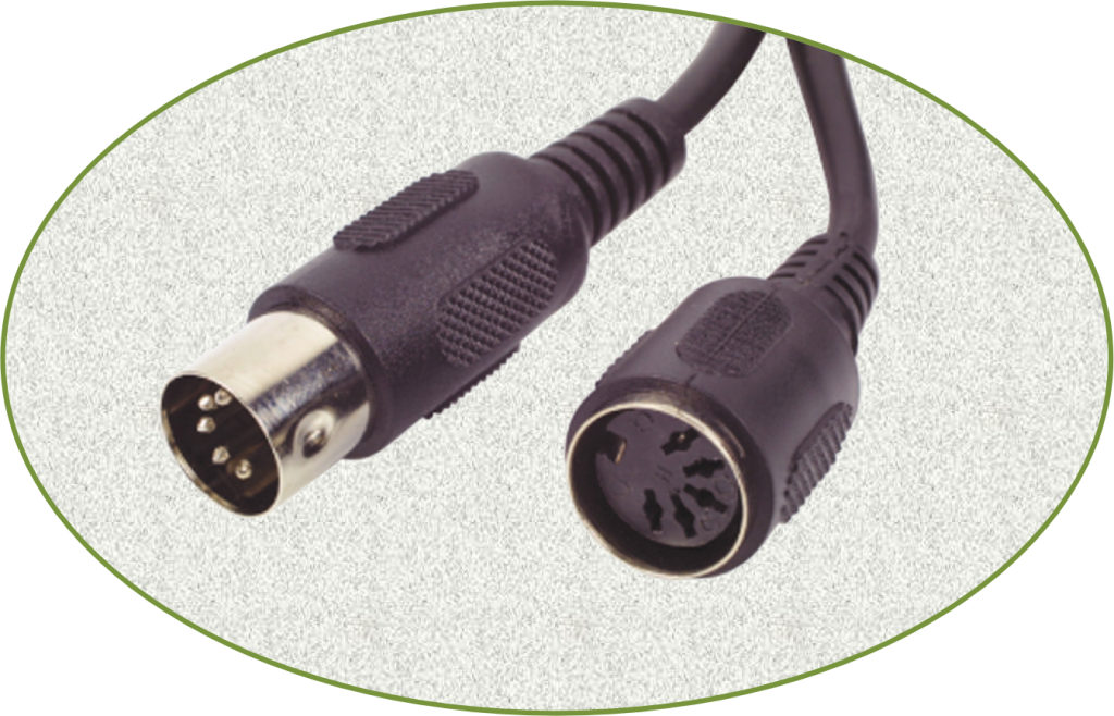
The MIDI connector is basically a 5 pin DIN connector and this type of cable is used to transfer MIDI data between components. MIDI, which stands for Musical Instrument Digital Interface is used to control MIDI devices such as a keyboard or a synthesizer. MIDI doesn’t create actual music. Rather, MIDI sends commands to the various electronic instruments and tells them to create the various sounds, pitch change, expression, et cetera. However, since this is not a section on MIDI, I’ll skip going into a lot about what MIDI does, except to reiterate that the MIDI cable allows for communication of MIDI data between electronic instruments, the digital interface, and the computer. It should be noted, if this type of cable were used to connect to your computer, it would, most likely, need to be converted to USB. Unless your digital audio interface converts it for you (I think most do, now) or you have a computer that had a dedicated MIDI port.
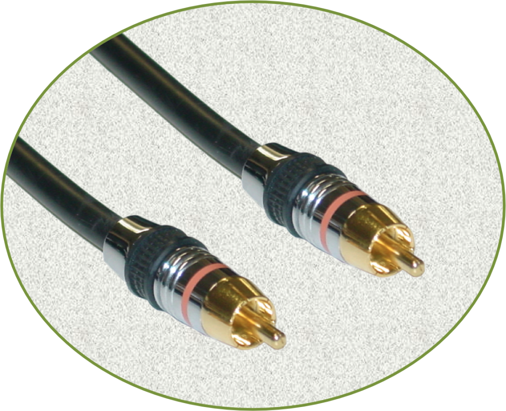
The RCA Connector (Phono Plug)
This connector, the RCA plug, also known as a “Phono plug,” is a staple in many homes around the world. It is the most popular type of connection for home stereo and home theater setups. It is also used on some studio equipment, particularly on portable gear. The connector is well suited for this role because it is a smaller connector than either an XLR or 1/4- inch Phone plug, and it is seemingly more durable the 1/8-inch phone plug. This connector is non-balanced.
This connector type typically carries analogue audio. However, This same type of connector can also carry analogue video (component) and if upgraded shielding is used, composite analogue video, and digital audio. With regard to the latter, you will often see these cables listed as “digital coax” or “digital coaxial” cable/connectors.
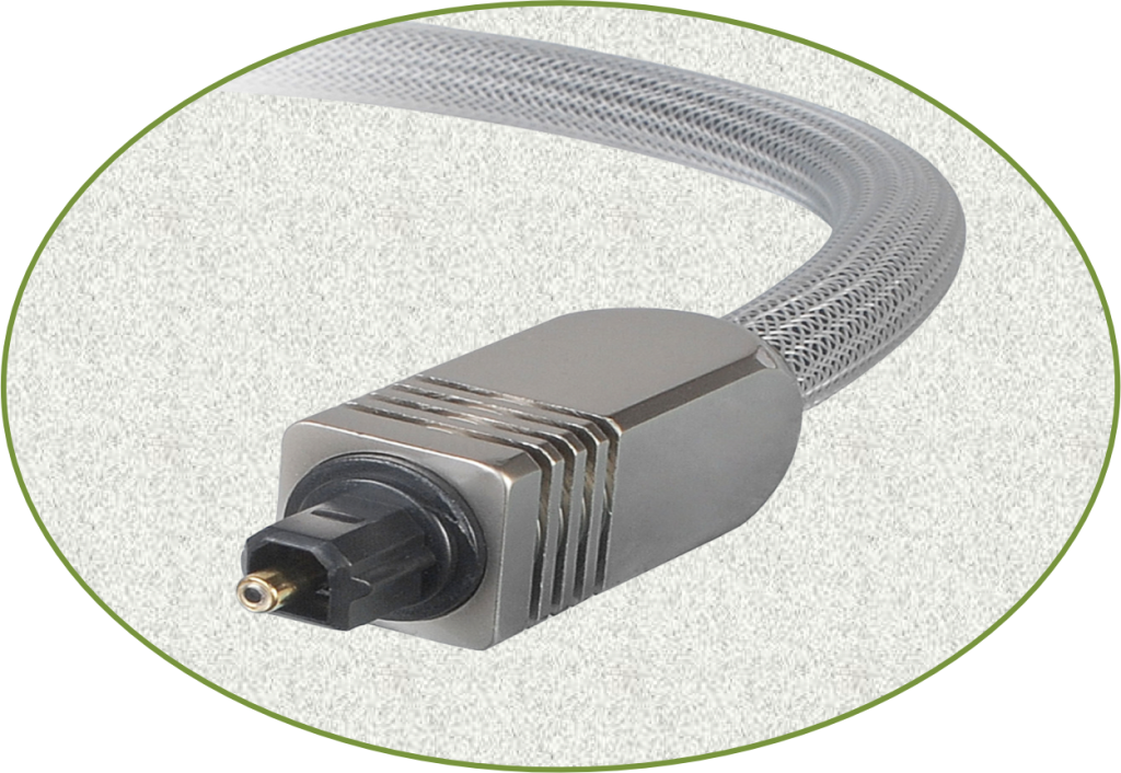
Fiber Optic (TOSLINK)
I always thought this was one of the neatest of all cables and connectors -the fiber optic TOSLINK. No copper here, just plastic and glass and one of the nicest things about optical is it typically not subject to outside interference. This wonderful means of sending audio is via light and it is a digital connection. You will see this connection on digital interfaces and some other components. Often, it is used as an alternate input or output to either an XLR or Phone plug. Additionally, you may also see along side of digital coaxial connection which used an RCA (Phono) connector.
Part II - The Patchbay
The Patchbay
A patchbay is a wonderful creation and a vital addition to a recording studio. However, while the average home studio might not need one, I thought I would tell you a little about them. I currently don’t have one but since I am in the process of re-cabling my setup, I thought I might add one. Why? What is the reason?
A patch bay, for the most part, is simply a point of access for a signal path. For example, let’s say your keyboard outputs (left and right) normally go straight to your digital audio interface. Now, let’s say a friend comes over and has her own keyboard she would like to use but, all of your connections are full on your digital interface and it is in a rack that is not easily accessible. What do you do?
The first thing you would have to do is gain access to either the back of the digital interface or the back of your keyboard but both of them are extremely difficult to get to. The solution is the patch bay.
Patchbays are nice, in the sense that they allow you to access the signal path. So for our friend’s keyboard, we would simply walk over to the patch bay and find the connection point for the keyboard. In this case we would want the outputs from patchbay to the interface. Now, what we are going to do is interrupt the signal path and inject the new signal from the keyboard owned by our friend. This is accomplished by simply plugging in the access point on the patchbay for the keyboard. Whoa, you say, that’s confusing. True, it does seem that way but it’s not really. Let’s take a look.
When looking at the image of a Sampson patchbay, you see two rows of 24 connectors. On the backside of the patchbay there are another set of two rows of 24 totaling 48. The easy way to think of a patchbay is to picture a metal “U” plugged into the front under “normal” conditions between the top and bottom rows. Now picture the back and in the top row there is a connection coming from say, our original keyboard and the output of the patch bay goes to our audio interface. In essence, under this condition, it is just like running your connection directly from the keyboard to the digital interface. However, in this case the signal passes through the patchbay.
So, our friend with her keyboard arrives and we want to record her. To gain access to the digital interface without unplugging anything, we simply locate the connection in the patchbay. For the sake of ease, we will say the first and second columns. Here we will plug the 1/4-inch balanced Phone plug in to the bottom plug 1 for the left channel and 2 for the right channel. When these plugs on connected the “normal” circuit from the normal keyboard is overridden and now the signal arriving at the digital interface is from the new keyboard. I quoted the word normal because this is what is known as a Normal, Normalled, Full, or Single connection.
Below is a .pdf document from Los Rios Community College District, California that illustrates what such a connection looks like, with regard to its internal workings. If it is confusing to you, don’t worry; I just posted it if you are interested in looking at the connection in a little more depth.
Patchbay Connectors Diagram
Lesson Projects
Project 1 - Designing Your Own Patchbay
Now we are going to have some fun. You remember, from Lesson 1, I showed you a basic layout of a recording setup. In that setup there was no patchbay present. However, there could be and will be because you get to design it and decide what plugs in where. Don’t worry about the computer or the digital audio interface at this point. Rather, focus on the originating components like the mic, keyboard, synthesizer, and effects processor. I should point out that the effects processor has many different ways to connect it. Therefore, don’t worry too much about getting it correct. The idea with this “Do” project is so that you can begin to think from a planning standpoint. If you can design my patchbay layout on paper, you can design your own when the time comes. Assume the connections will all be Normalled (refer to the Patchbay Connections diagram .pdf), we go into the other types of connections in greater detail later. Please refer to the Lesson Resource Links at the bottom of this page for additional diagrams. The instructions follow:
- Locate and print the “block diagram” of my current keyboard setup from lesson 1.
- View and print the image of the patchbay in this assignment. I have added a .pdf image to make it easier for you to print.
- Locate and download the PDF file “Patchbay Connection Sheet.” This will be your master sheet with each number representing a connection to and from the patchbay. I created this sheet as a form so, if you open it in Acrobat Reader you should be able to fill in the form fields right from your computer keyboard. You can highlight the form fields by clicking the button “Highlight Existing Fields.”Remember the upper bank is the “IN,” or from the components to the patch bay, and the lower bank is the “OUT,” or from the patchbay.
- Look at the image of the patchbay and then use the numbers of on the Word document to write your connections.
- When you have finished, email me a copy of your word document and I will review it for you and will make suggestions as needed.
As an example, you might have the cable from the left channel of the Keyboard coming into Connection 1 on the patchbay. Connection 2 has the cable from the Right channel of the Keyboard. So, your connection sheet might look something like:
- Left Keyboard 2. Right Keyboard
Remember, all of these connections plug into the rear of the patchbay and all, at the moment, would be on the top row. Don’t worry about the lower bank (right side of the connection sheet) in this lesson because we haven’t talked about the digital interface which is wear most of these lower bank connections will terminate.
This is not a graded assignment. Rather, as stated earlier, it is just designed to help you get to thinking into a planning state of mind.
Project 2 - Making a 1/4 Inch Balanced TRS Phone Plug Patch Cable
The suggested materials for this project are as follows:
- Soldering Iron (approximately 20~30 Watts)
- Rosin Core Solder. Thinner is better in this case. Should be available at stores like Home Depot, Lowe’s.
- Wire cutter/wire strippers.
- A vice or other clamping device like the “Helping Hand Tool” this can be purchased through Amazon but other stores will probably carry it as well.
- Soldering iron stand. This is a place to keep your iron while its hot. You could improvise this, I used to use an old ashtray years ago. However, the stands are very handy.
- Cable. Use your own judgement on this, you might want to practice before making your official connection. I would say 20 to 50 feet but this is just suggestion.
- Connectors. x 2 – 1/4 inch TRS Phone Plug (male)
- Optional – cable tester. Likewise, you can also use an ohm meter if you have one.
- Finally, safety glasses. Wear you safety glasses.
NOTES:
1. At the bottom of this page, in the “Resource Links” section, there is a pdf file that you can view download and print. It contains the 1/4 inch TRS Phone Plug and many other connectors and adapters. This is a great reference. While you might not want to tackle some of those other connectors, it will provide you with further study on the subject of soldering and connections.
2. Since you should have excess cable, experiment with cutting, stripping, and tinning the cable ends. You may think this is easy, and in many respects it is, but like anything, practice makes perfect.
Video for Soldering a Patch Cord Connection
Below is a YouTube video that illustrates how to solder a 1/4 inch TRS connector. The video contains no audio. However, it does layout the following guidelines that you should adhere to:
- Clear your work area
- Turn on soldering Iron
- Setup your vice or clamp
- Ready the solder
- Put on your safety glasses now
It is possible that you will not know what some of this means. If this is the case, please post questions to the forum or email me. It is also possible that some of your classmates will be able to assist you via the forum.
Discussion Board Forum
Quiz - Lesson 2 Connectors and Patchbays
Click the button, “Start Quiz,” to begin this test of six questions.
Summary
Lesson Summary
I hope you thought this was an interesting lesson. I know it most likely wasn’t the most thrilling but the information is important. Not only did you review or learn about some of the most common connectors in the recording studio, but also you had an introductory lesson in a patchbay setup.
Perhaps, the most important thing to remember about patchbays is that they are always (or should always be) top incoming from components and bottom outbound away from the patchbay. In addition, they should always be labeled or have a listing similar to the one you created, listing all of the connections and their associated port(s). We will revisit the patchbay and also connections in future lessons.
Finally, you created a soldered connection to a cable. If this was your first solder connection, congratulations. If you’ve made solder connections in the past then I hope this served as a review and that you got something out of it. There are many variations to soldering and as you practice and become more proficient you will adapt to whatever method suits you best. The primary idea of this hands-on lesson was to give you a point of origin; that is to break ground on the world of soldering connects. By the way, making your own cables can save you a lot of money and you know, first hand that they meet your specifications.

